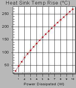
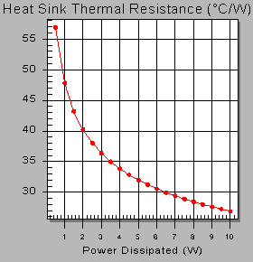
The performance graphs in this on-line catalog fall into two categories: forced convection and free convection. The two free convection graphs are used to show heat sink performance when used in a natural convection environment (i.e. without forced air). The horizontal axis represents the heat or power dissipated (watts) and the vertical axis shows either heat sink temperature rise above ambient or the effective thermal resistance. By knowing the power to be dissipated, the temperature rise of the mounting surface can be predicted. Thermal resistance is determined by dividing this temperature rise by the power input (°C/W).
Free Convection

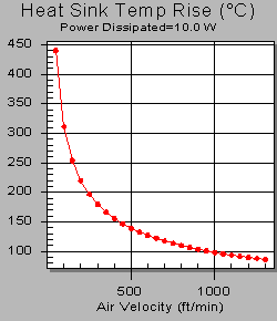
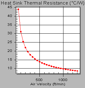
The two forced convection graphs are used to show heat sink performance when used in a forced convection environment (i.e. with forced air flow through the heat sink). The horizontal axis represents the air velocity over the heat sink (LFM or m/s) and the vertical axis shows either heat sink temperature rise above ambient or the effective thermal resistance. By knowing the air velocity, the temperature rise of the mounting surface can be predicted. Thermal resistance is determined by dividing this temperature rise by the power input (°C/W).
Forced Convection


